Last weekend we performed tests of our transceivers using different antennas and data transmission rates.
We tested two different antennas on the transmitting side (the equipped one and a simple wire) and two on the receiving side (the equipped one and a large directional one). All tests were performed with a 9600 baud rate.
We started by testing the equipped antennas to determine the safe data rate — one that would result in no or minimal data loss. While the guide recommended using 60% of the baud rate — which would be 5760 bits per second for 9600 baud — we discovered that it still resulted in minor data loss when transmitting data on a distance on about two-three metres and decided to use 5000 bps, which resulted in no losses.
We constructed two testing sets using the transceivers which could have their antennas easily swapped and rugged them against wintery conditions, so they could be used outside. They also allowed us to reprogram the transceivers to use a different baud rate, although we never used this feature.
Michał wrote a pair of Python scripts to test data transmission and integrity of received data. One would send a series of numbers via the serial interface, starting at one, repeating each one twice, at chosen speed; the other would receive data, display information about number of received items, and compare their validity (whether one number of the pair matched the other).
Test 1
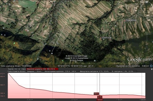
We placed the transceivers on two hillsides facing each other, on a distance of about 1050 m. We were transmitting data using the equipped antenna and receiving it with the large directional one.
We performed all tests using 9600 baud rate with 5000 bits sent per second.
In a series of tests, we discovered that although there are no concerns about data integrity nor data loss at this distance with this hardware, the antenna only provided a range of about 90 degrees horizontally and 60 vertically; when directed outside this range, it sharply stopped receiving any data.
This prompted us to conduct another test at a larger distance, and to test the capabilities of equipped antenna as a receiver.
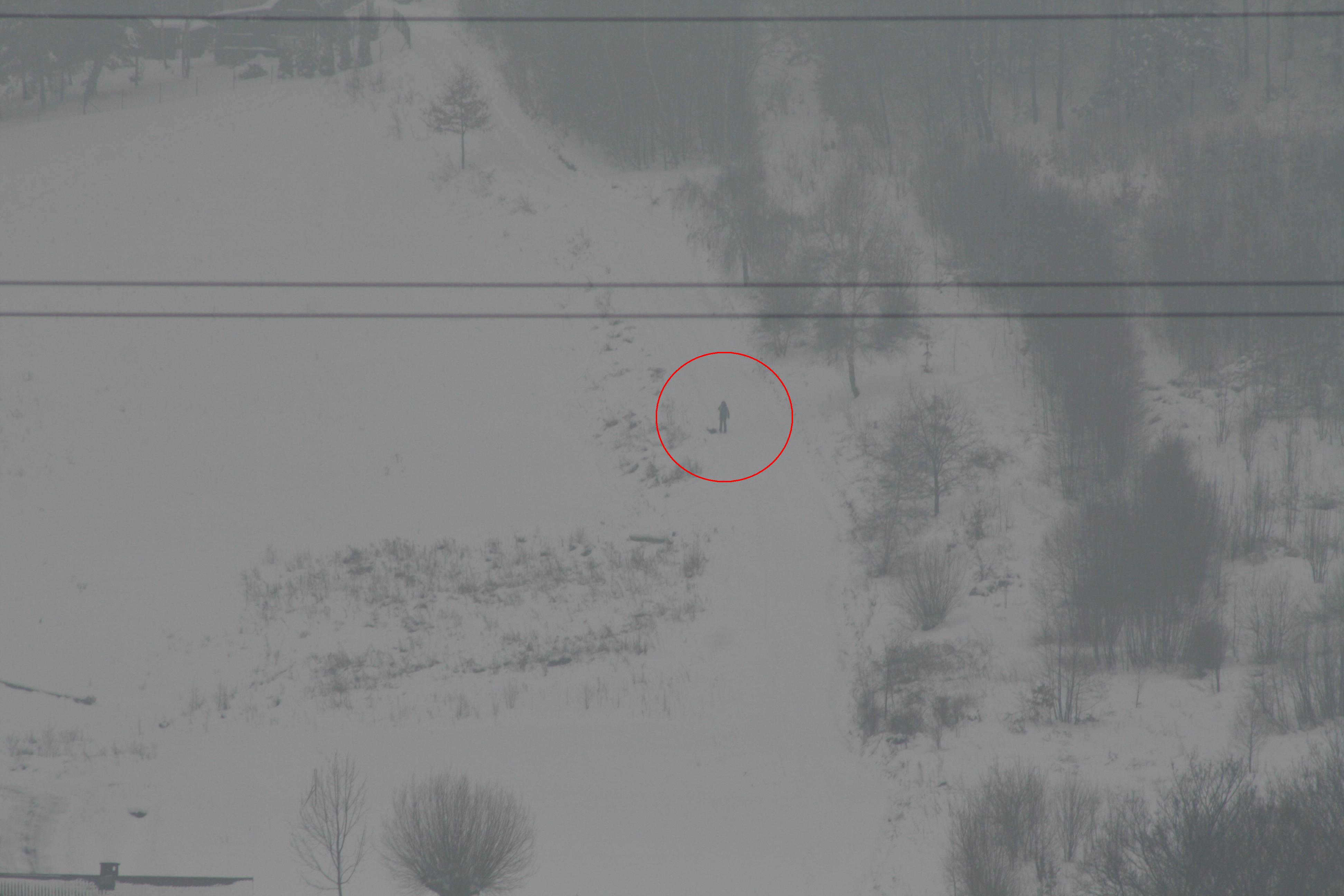
Łukasz as seen from Bartosz’s position
Test 2
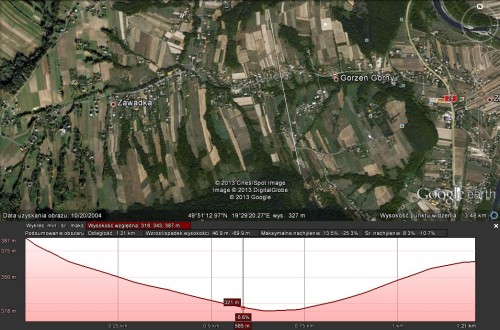
We placed the transmitter on a large hill (approx. 300 metres prominence) and the receiver on a plain below it.
At first we tested all combinations of antennas, on a distance of about 800 m. We confirmed the large antenna results, and we discovered that the equipped antennas were able to talk to each other on this distance with virtually no data loss. We received almost no data from the simple wire-based antenna, though.
Afterwards we tested the large antenna on a distance of about 1500 m. It was able to receive data with no losses regardless of the direction it was pointed at, proving that it has a minimal range it can operate at. While we managed to receive data with the equipped antenna as well, we had approximately 20% data loss, making it unviable for our purpose.
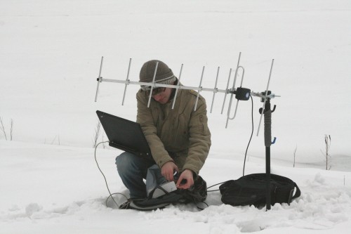
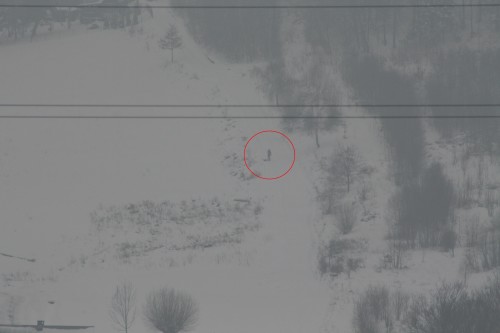
Bartosz with the large antenna